
Continuing on from my post about the GAP Titan; it did a decent job of putting out a signal out on 40 meters, at least as far as the Reverse Beacon Network was concerned. Several times I would call CQ and notice that I was getting into Europe quite well but I was not getting any replies. Or, I finally would get a response, but the other op was so hard to copy that I spent more time fiddling with various controls on the radio trying to get a copiable signal than trying to comprehend what he is saying. Frustrating: I had to keep turning the power on the transmitter down so that I would cover a smaller area increasing my chances of actually hearing responses. On 20 meters, I could not seem to hear much and didn’t light up the RBN much either.
Yes, I could frequently work what I heard but that is saying very little. My inefficiency is terrible. This had me contemplating replacing the vertical with an non-resonant doublet. With the sunspot cycle the way it is, I need longer wires to pick up those faint signals. The problem is going to be that most of the wire will be way too low to the ground meaning ground losses will be huge. I guess the earthworms will be happy if they like warm environments. If I could determine my back yard’s electrical parameters, I could probably accurately model how things will be. Trying various parameters is interesting and it is probably just as well that I do not know the accurate values; I would probably be very disappointed.
According to the ARRL Antenna Book, a non-resonant dipole of 88-feet length can be effective. They also say that placing it high in the air is important. Guess that is not going to happen. I made some measurements and found that 88 feet between a chimney and the back corner of our backyard would just fit. Let’s take a look at a model estimating the height above ground it will be.
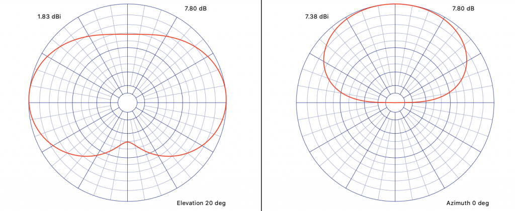
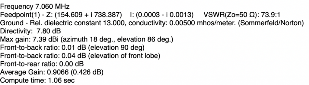
Whoa! Feedpoint impedance is unbelievable. Frequencies in other bands are not much better. What to do?
In a moment of madness, I decided to do it. I started rounding up the various pieces that I would need. The main thing was a tuner to try to deal with that monstrous mismatch; my poor Kenwood certainly cannot deal with that.
Working slowly away all afternoon, this eventually appears.
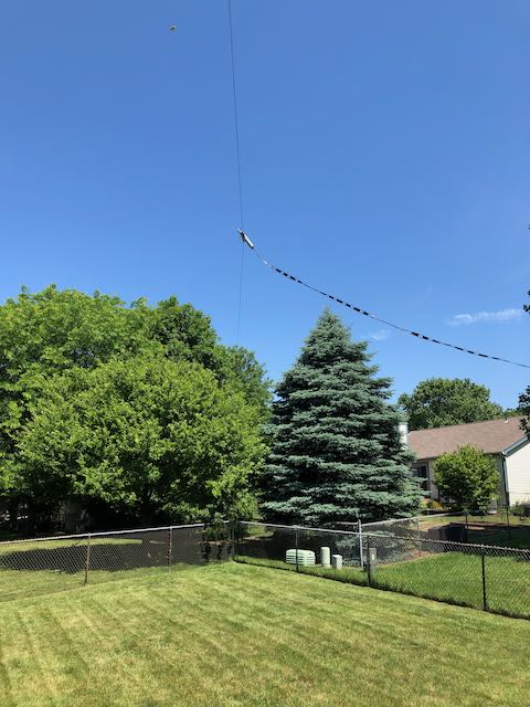
This is looking toward the back corner of our yard. The feedline was about 80 feet of 450-ohm ladder line that was, at first, threaded around the gazebo, over to near the back outer wall of the house, down through the foundation plate and over to the tuner near my radio. Gee, I just can’t wait to pull in those stations!
The moment of truth finally arrived and I started to get used to working the tuner (never had to do that before). The few signals I heard were watery and tuning is very touchy. I was able to get a match but calling CQ on 40-meters gets no spots. There were a couple of contests and other events going on and calls to several stations at max power (100 watts) yields no answers. Oh no – what is wrong? What I have done? This thing is useless!
It was a sleepless night, more so than usual. How could this be? Getting the Titan back up would be a huge undertaking. It was a mess; partially damaged in a big wind-storm several years ago and needing much clean up and re-building. I do not have the stomach for that.
The next day, I thought about taking my current balun from inside to outside and take out a section of the ladder line. Fortunately, I still had the coax to the Titan to connect to the new location of the balun. With wire cutters in hand, I closed my eyes and lopped off about half of the ladder line and put the balun in place. Wow, what a difference! That works! Unfortunately, the balun is not outdoor rated but I was able to trade it for one that is.
So how are we looking? Here is a look for the Reverse Beacon Network:
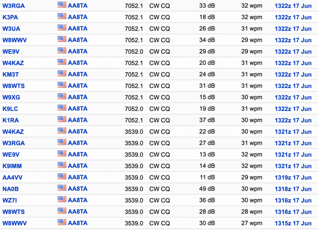
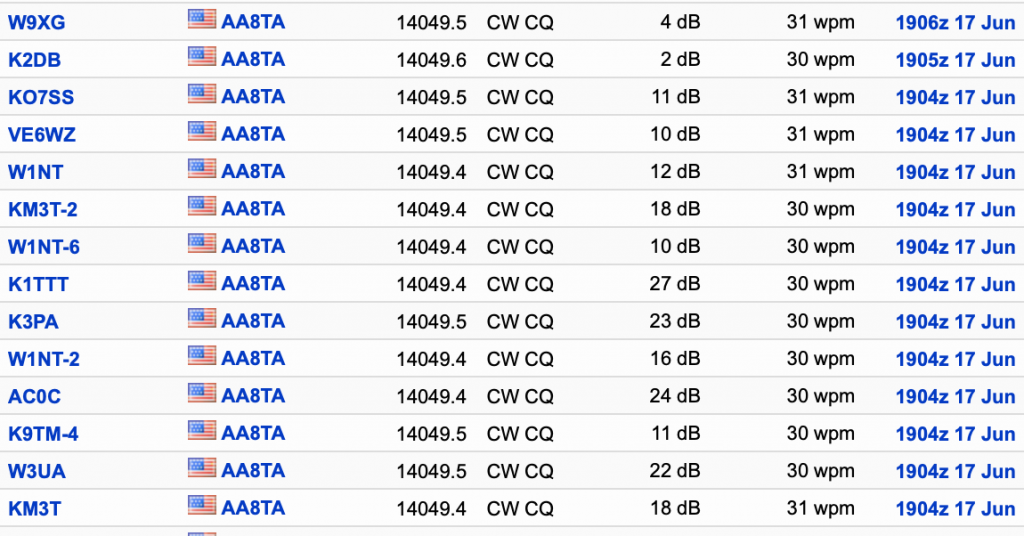
This shows me running in a CWops Mini Test (CWT) on 40 meters, 80 meters (morning session) and 20 meters (afternoon session). S/N ratios of 7 to 49 dB are looking pretty good. I have a lot more RBN data from many other days and times also looking good. I used to get out almost nothing on 20 meters.
How about that matching? Before it was looking pretty bad. Here is a SWR plot from an antenna analyzer.
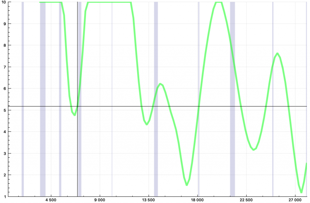
Not great, but it is non-resonant. At the lower end of 40 meters, things measure 25.6 +j61 ohms; inductive, but that makes sense. That’s a lot different than the model showed – wonder why?
Let’s try fiddling with the model a bit. Here is a revised model taking into account the ladder line:
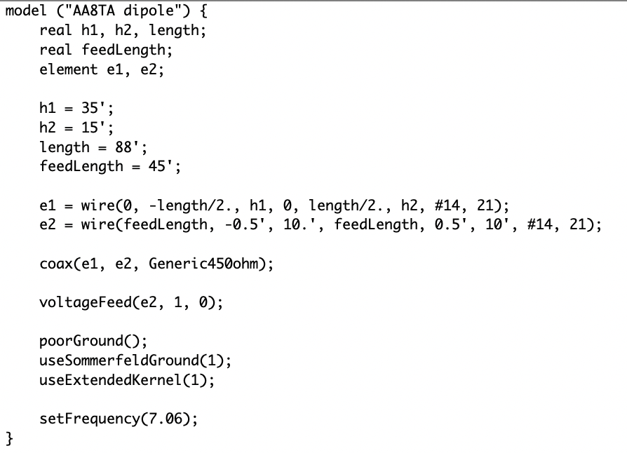
This is modeling program called cocoaNec for Apple Macs. I use an NEC 4.2 engine with this (which I had to compile from Fortran). Now the impedance parameters show:
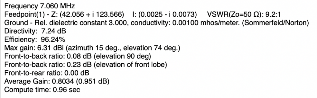
So we are getting closer. I cannot account for the metal chain link fence around the yard, the house and other stuff going on. My 6-meter halo is uncomfortably close underneath the dipole. The stuff one has to live with.
But, so far, so good. I still need to tune the model and see if something can be done moving the feedline around to shift the resonant dips. But this is fun!