My 6-meter halo antenna

(The following was written for my local club’s newsletter in the summer of 2016.)

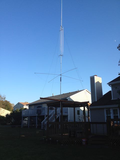
The ARRL June VHF Contest was approaching so I decided to see if I could load my GAP Titan on 6 meters.  It matched pretty well though probably not very efficiently.  I managed to work 13 stations covering Texas, Florida, Louisiana, and Ohio, all on CW.  Woo hoo! Only 46 states to go for 6 meter WAS.

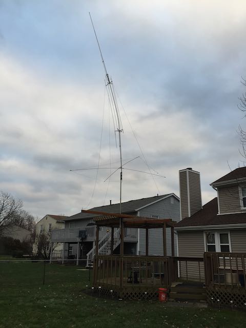
Subsequent to that, I took the Titan down and re-tuned it from 75 meters to 80 meters.  For the CQ July VHF Contest, the SWR on 6 meters was not very good, the transmitter folded back and the tuner was necessary.  Only worked three stations, all in Ohio.  I think propagation had more to do with those results than the antenna.

So I started thinking about a real 6-meter antenna.  Given my cramped space, I thought a halo antenna might work.  A halo is a half-wave dipole formed into a circular shape and fed with a gamma match.  I found a QST construction article on a halo and tried it out.  Mechanically, it was kind of flimsy and I could not get a decent match below 53 MHz.  So that idea was scrapped and I found another article written by Carol Milazzo, KP4MD, and Version 2 was started.

This version uses 112 inches of ¼ inch soft copper tubing for the dipole, ½ inch PVC tubing for the support structure, an 18-inch piece of #10-gauge wire for the gamma match and a 200 pF, 1 kV ceramic disk capacitor to feed the matching rod.

This picture shows the initial construction.  The halo is more ellipsoidal instead of circular.  I should have done a test fitting before gluing the PVC parts together.  Oh well, hope it isn’t too directional.

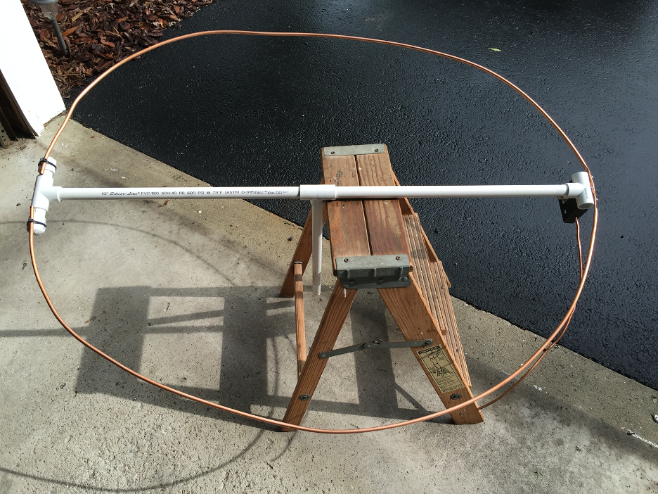
I temporarily attached the far ends of the dipole to the support structure using tie-wraps for tuning later on.  Next we see the small plastic box that holds the SO-239 connector, the 200 pF capacitor and one end of the matching rod.

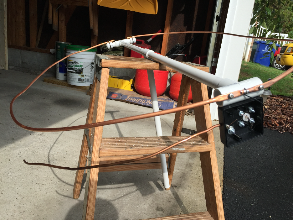
After putting it together, we end up with this.  There is a shorting clip 12 inches out along the matching rod.  For tuning purposes, the shorting rod is actually two alligator clips connected together which will subsequently be replaced with a piece of copper wire.  Yea, it’s none too pretty but, then, neither am I.

Tuning consists of adjusting the gap between the far ends of the copper tubing for lowest SWR at the desired frequency then adjusting the position of the shorting bar and the value of the coupling capacitor to try to get to 1:1.  Without an antenna analyzer, I had to rely on my rig’s SWR meter and my forward/reverse power meter.  After about 30 trips in and out of the house, I got the SWR down to about 1.2:1 from 50.2 MHz to around 50.5 MHz.  It’s under 1.5:1 from 50 MHz to over 51 MHz.  Good enough for me.  Before putting it up, I took a couple of inches out of the cross pieces to make the loop more circular.

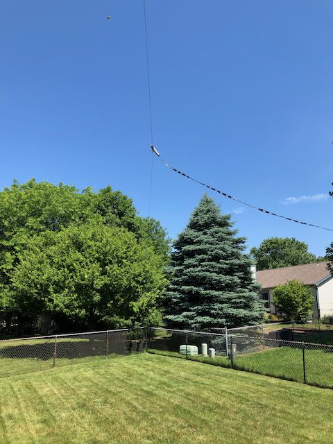
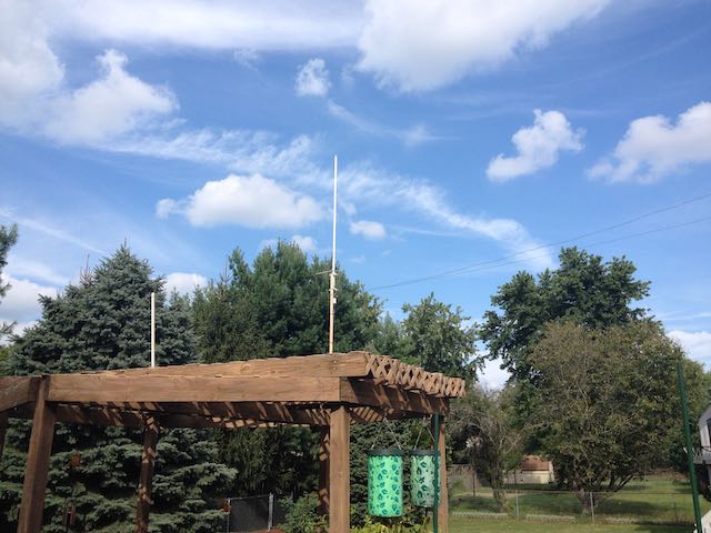
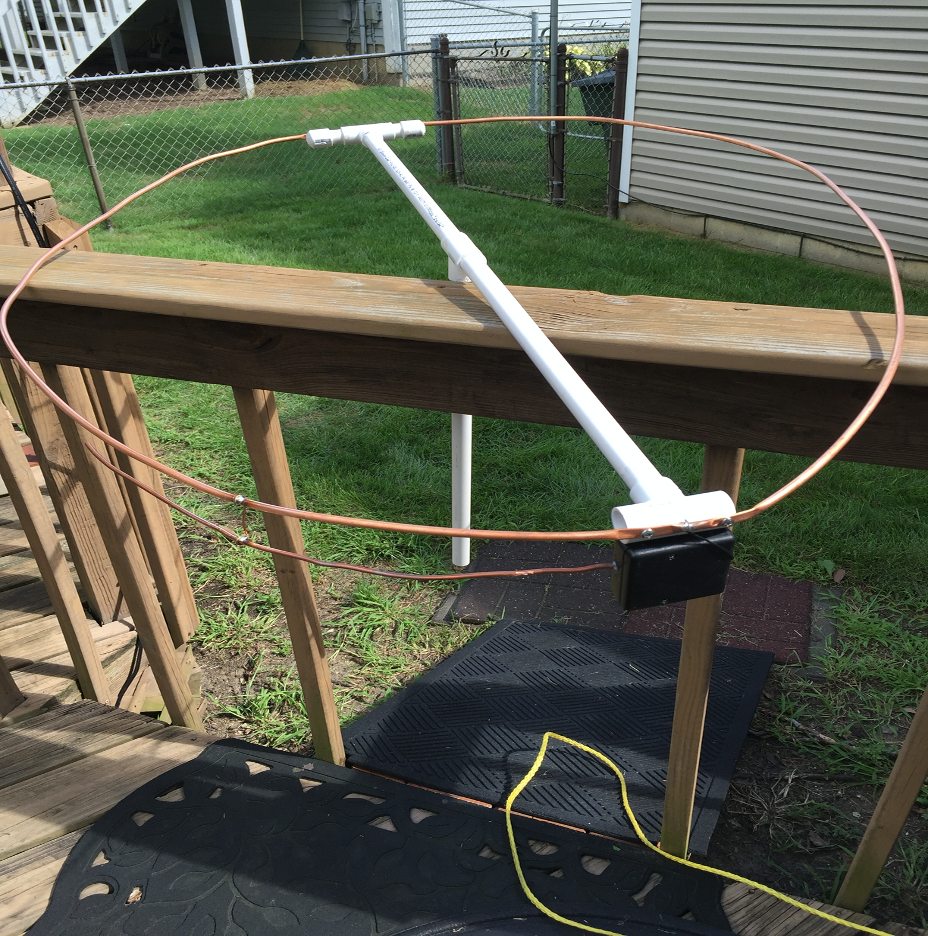
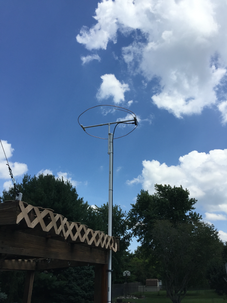
Here we see the final product mounted on our gazebo.

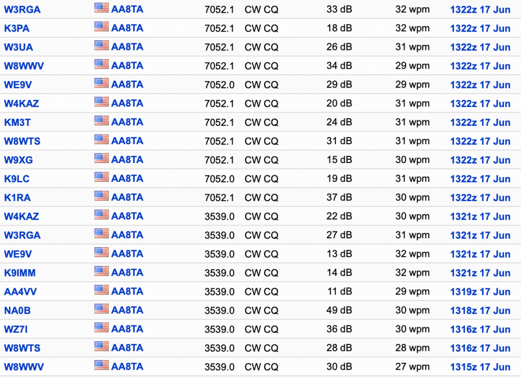
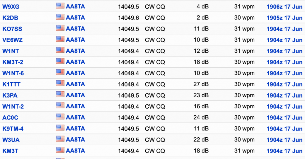
So how does it work?  Any time I putter around with antennas, I always make a few CQs on CW and see where I get picked up – and how well – by the Reverse Beacon Network (RBN).  On this particular day, there were only two RBN monitors on-line, one in Germany and the other in Spain – rats!  6-meters was as dead as my grass before a recent bout of rain and no beacons were heard either.  Did hear some strange signals which I wondered were some kind of birdies from something.  Later on, I did hear a beacon from near Hamilton, Ohio, although it was weak.  But, there was the ARRL September VHF Contest coming up.

In the September 6-meter contest, I made all of two – TWO! – contacts; both in Franklin County.  I also found out that this thing doesn’t like rain – when it is wet, the SWR is dreadful.

Total cost: about $20 for the tubing, PVC, plastic box and other miscellaneous items.  I ran about 60 feet of RG-8/U cable into the shack along with a bulkhead connector, a surge protector and a handful of connectors (seems I’m always out of PL-259s).  The cable cost far more than the antenna.

Well, it’s no beam but I’m on 6 meters.

Update: Since I put up this halo, I have confirmed 21 states, including Colorado, South Dakota, Texas and some of the east coast area. I have also gotten as far as the Bahamas. Sometimes, the band opens up quite well and sometimes it is hard to get much further than about 30 miles.

The current wisdom is that the introduction of the FT digital modes has sucked the CW and SSB life out of 6 meters. I’m not very active on the Magic Band but there was a recent VHF contest where things were pretty good at times. I can only imagine what a higher antenna would do.

My third HF antenna

Continuing on from my post about the GAP Titan; it did a decent job of putting out a signal out on 40 meters, at least as far as the Reverse Beacon Network was concerned.  Several times I would call CQ and notice that I was getting into Europe quite well but I was not getting any replies.  Or, I finally would get a response, but the other op was so hard to copy that I spent more time fiddling with various controls on the radio trying to get a copiable signal than trying to comprehend what he is saying.  Frustrating: I had to keep turning the power on the transmitter down so that I would cover a smaller area increasing my chances of actually hearing responses.  On 20 meters, I could not seem to hear much and didn’t light up the RBN much either.

Yes, I could frequently work what I heard but that is saying very little.  My inefficiency is terrible.  This had me contemplating replacing the vertical with an non-resonant doublet.  With the sunspot cycle the way it is, I need longer wires to pick up those faint signals.  The problem is going to be that most of the wire will be way too low to the ground meaning ground losses will be huge.  I guess the earthworms will be happy if they like warm environments.  If I could determine my back yard’s electrical parameters, I could probably accurately model how things will be.  Trying various parameters is interesting and it is probably just as well that I do not know the accurate values; I would probably be very disappointed.

According to the ARRL Antenna Book, a non-resonant dipole of 88-feet length can be effective.  They also say that placing it high in the air is important.  Guess that is not going to happen.  I made some measurements and found that 88 feet between a chimney and the back corner of our backyard would just fit.  Let’s take a look at a model estimating the height above ground it will be.

Whoa! Feedpoint impedance is unbelievable.  Frequencies in other bands are not much better.  What to do?

In a moment of madness, I decided to do it.  I started rounding up the various pieces that I would need.  The main thing was a tuner to try to deal with that monstrous mismatch; my poor Kenwood certainly cannot deal with that.

Working slowly away all afternoon, this eventually appears.

This is looking toward the back corner of our yard.  The feedline was about 80 feet of 450-ohm ladder line that was, at first, threaded around the gazebo, over to near the back outer wall of the house, down through the foundation plate and over to the tuner near my radio.  Gee, I just can’t wait to pull in those stations!

The moment of truth finally arrived and I started to get used to working the tuner (never had to do that before).  The few signals I heard were watery and tuning is very touchy.  I was able to get a match but calling CQ on 40-meters gets no spots.  There were a couple of contests and other events going on and calls to several stations at max power (100 watts) yields no answers.  Oh no – what is wrong?  What I have done?  This thing is useless!

It was a sleepless night, more so than usual.  How could this be?  Getting the Titan back up would be a huge undertaking.  It was a mess; partially damaged in a big wind-storm several years ago and needing much clean up and re-building.  I do not have the stomach for that.

The next day, I thought about taking my current balun from inside to outside and take out a section of the ladder line.  Fortunately, I still had the coax to the Titan to connect to the new location of the balun.  With wire cutters in hand, I closed my eyes and lopped off about half of the ladder line and put the balun in place.  Wow, what a difference!  That works!  Unfortunately, the balun is not outdoor rated but I was able to trade it for one that is.

So how are we looking?  Here is a look for the Reverse Beacon Network:

This shows me running in a CWops Mini Test (CWT) on 40 meters, 80 meters (morning session) and 20 meters (afternoon session).  S/N ratios of 7 to 49 dB are looking pretty good.  I have a lot more RBN data from many other days and times also looking good.  I used to get out almost nothing on 20 meters.

How about that matching?  Before it was looking pretty bad.  Here is a SWR plot from an antenna analyzer.

Not great, but it is non-resonant.  At the lower end of 40 meters, things measure 25.6 +j61 ohms; inductive, but that makes sense.  That’s a lot different than the model showed – wonder why?

Let’s try fiddling with the model a bit.  Here is a revised model taking into account the ladder line:

This is modeling program called cocoaNec for Apple Macs.  I use an NEC 4.2 engine with this (which I had to compile from Fortran).  Now the impedance parameters show:

So we are getting closer.  I cannot account for the metal chain link fence around the yard, the house and other stuff going on.  My 6-meter halo is uncomfortably close underneath the dipole.  The stuff one has to live with.

But, so far, so good.  I still need to tune the model and see if something can be done moving the feedline around to shift the resonant dips.  But this is fun!

My second HF antenna

My first HF antenna, an off-center fed dipole for 40 meters, lasted about 6 months until September, 2014. At that time, I decided to go to a GAP Titan, a multi-band vertical. Here it is after a day of assembly.

I also ordered an aluminum tilt-over assembly, which is attached to the gazebo behind our house. I found out later that I could get by without using the tilt-over feature but that was OK.

The 40 meter radial hoop was about 25 feet above the ground. As for performance, I expected a low take-off angle which I was hoping for for DX. That is pretty much the way it worked out and I quickly got a lot of the Caribbean area and Europe.

80 meter performance was not so good, as expected for a compromised vertical. But I was generally OK with how it did, especially since I could not get anything longer or higher.

I was concerned about the aluminum tubes supporting the horizontal hoop so I stuck dowel rods in them to stiffen them up. I also bought a guying kit from GAP and used Dacron line to guy the Titan around the gazebo. Later on, I used fishing line to add further support to the ground hoop.

The Titan had not been up for very long before disaster struck.

This was around Thanksgiving, 2014, after a nasty blast of wind roared through. The constant gusting of wind had caused one of the guy lines to loosen up from the vertical part of the Titan and the center part bent over. Clearly shows how important guying is.

I lowered the Titan to ground and managed to mostly straighten the center part and re-raised it. After that, I noticed that SWR on 12 meters was rather poor so I climbed up to add a short length of #14 wire to one of the tuning rods which helped. It might have been when the Titan was down that I added the fishing line.

After another year, I became a full-time CW operator and had a great deal of difficulty tuning the CW part of 80 meters. There is a tuning capacitor at the very top of the Titan that is set at the factory to the higher end of 75 meters. I ordered a different capacitor from GAP and swapped it for the existing one.

That necessitated taking the Titan down again and this time I also further straightened the center mast.

The Titan did work on all bands from 80 meters to 10 meters without a tuner, although 12 meters always had SWR over 2:1. I could even use it on 6 meters and managed to get into some 2 meter repeaters with it.

The Titan always seemed to really rock on 40 meters. It was OK on 80 meters but I seemed to struggle much of the time on 20 meters. Eventually, the sunspot cycle that I enjoyed so much in 2014 and 2015 started to wind down and the higher bands were not as easy to use any longer. It got to the point that 40 meters was about all I used.

One data point was operating in the Ohio QSO Party: in this, picking up Ohio counties as multipliers is pretty important to getting a decent score. I noticed that picking up Ohio counties on 80 meters was not easy; getting out to Wisconsin was. Similarly, on 40 meters, getting to the mid part of the country was easy but picking up more local contacts was a challenge.

Whenever we got a storm roar through or the winds got somewhat violent, which happens a few times a year, I would watch from our kitchen window as the Titan got battered around. I was always so afraid of a repeat of what happened in 2014 where a guy line would loosen up and the already weakened Titan would droop over the neighbor’s fence. I was also concerned about a big ice storm causing damage. Fortunately, those did not happen.

Eventually, I grew frustrated with the lack of ears on 20 meters and thought that, maybe, better performance could be obtained with wires. Another factor was the thinking that we are not going to be at this house much longer and taking the Titan down would be a chore, especially with me getting older and less physically able to mess around with it. This led to a decision that was executed in June, 2020, to retire the Titan and go with a non-resonant doublet.

More on that later.

My first HF antenna

After over 35 years, I finally got back into amateur radio early in 2014. This represented my first experience with HF. My first antenna was an off-center fed dipole, about 20 feet or so above the ground. It was about 65 feet long, started at a chimney on our house and ran down to a post at the back part of our lawn. The feed point was attached to a PVC pipe attached to the side of our gazebo.

Off-center fed dipole.

It tuned without and external tuner on 40, 20, 17, 12 , 10 and 6 meters. I don’t remember if it worked on 30 meters. I don’t think I ever used the internal tuner on my radio. It definitely would not tune on 15 meters.

Since 2014 was around the last solar maximum, I put another off-center fed dipole cut for 15 meters under the longer wire. I don’t remember how that was connected at each end but the two dipoles shared a common feed point.

Coax was used as the main feed line. A commercial choke, consisting of a short length of coax with ferrite beads surrounding it, was used.

Performance was not great, it was fairly good for local contacts, as expected with it being so close to the ground. I was able to work some DX although nothing sticks out. I was active on phone and digital, mostly JT65 and JT9.